Installation Instructions
General
Track accessories are dependent on the track structure to which they are secured. Worn, small or weak ties flex under traffic. Untamped ties can cause excessive vertical torquing. Any switch point guard attached to an inadequate track structure will give poor service and may be subject to premature failure. Be sure the track is in sound condition before installing the Model FM, or any switch point guard.


Installation Without Bolting To Rail
Basic Units Only

  1. Be certain section of rail corresponds to that identified on the manufacturer's plate attached to the Model FM. Each unit is made to accommodate one rail section only.
  2. Check to see that track gage is not tight.
  3. Be certain stock rail has full head width at the point. Excessive railhead side wear can cause derailment.
  4. At switch, jack the rail sufficiently to remove existing slide plates.
  5. With rail elevated, position Model FM in appropriate location.
  6. Adjust ties for proper spacing and insure that ties are at right angles to stock rail.
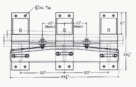
  7. Lower the rail, insuring that stock rail base rests ("beds") in seats on Model FM Slide Plates. No portion of stock rail base should be on top of Model FM Riser (See Fig. 10).
  8. Tighten all Wear Bar retaining bolts.
  9. Spike Model FM securely


Installation With Bolting To The Rail

  1. Perform Steps 1, 2 and 3, listed above
  2. Referencing guidelines provided by Fig. 8 and Fig. 9, locate and mark on the stock rail, the horizontal center lines of the optional mounting bolt holes.
  3. Locate and mark the vertical hole centers using the scribe furnished with the unit. Drill two 1-1/8" diameter holes (Oversize holes can result in bolt head failure).
  4. Perform Steps 4, 5, 6 and 7, listed above.
  5. With thw Waer Bar removed, install the two 1" dia. thin-head track bolts - head toward gage (Refer to Fig. 10) and tighten.
  6. Replace the Wear Bar (See Fig. 2 for proper assembly). Tighten all Wear Bar retaining bolts.
  7. Spike securely


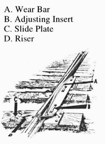
Fig. 7
Key Components


Fig. 8
Model FM showing position of track bolts.


Maintenance
Inspection/Adjustment

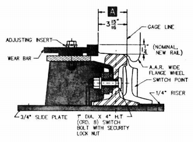
Occasional inspection for wear and bolt tightness are the only regular maintenance requirements. When Dimension "A" shown in Fig. 10 measures 4-3/16" to 4-5/16", the Adjusting Inserts should be unbolted and turned (See Fig. 2). Doing so will provide an additional 1/4" wear capacity. Do not turn Adjusting Inserts until Dimension "A" measures at least 4-3/16", or the Wear Bar may cause train wheels to bind against the opposite rail from point.

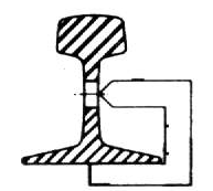
Fig. 9
Scribe in use, for locating bolt holes vertically.


Fig. 10
Slide view of installed Model FM Switch Point Guard,
showing critical dimensions.

Grinding ----
Manganese steel is a work-hardening material. In its original condition, it tests about 230-250 bhn. After "wearing in", it will achieve a surface hardness of up to 550 bhn. During this process, the material will have a tendency to flow. Depending upon service, sometimes a ridge or groove will develop. The Wear Bar should be ground carefully to remove only the flowed material, but not the already hardened portion. More than one grinding may be required before the material is set and hardened to capacity. Lighter initial service, lessens the need for grinding. Heavy impact from long cars on tight curves will result in a requirement for more frequent grinding.
Back to main switch point guard page